
Introduction to LM393 Sound Sensor
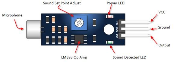
The LM393 Sound Sensor is a compact and highly sensitive module designed to detect sound levels in the surrounding environment. It consists of an electret condenser microphone, an amplifier circuit, and an LM393 dual comparator IC that converts sound vibrations into readable electrical signals.
The sensor provides both Analog and digital outputs, making it useful for a wide range of applications.
· The Analog output (A0) gives a continuous voltage proportional to the intensity of the sound.
· The digital output (D0) provides a simple HIGH/LOW signal whenever the sound level crosses a user-set threshold, which can be adjusted using the onboard potentiometer.
Because of its fast response, low power usage, and adjustable sensitivity, the LM393 sound sensor is widely used in projects such as clap switches, noise- activated alarms, voice-controlled lighting, smart security systems, and environmental noise monitoring. Its simplicity and reliability make it an excellent choice for both beginners and advanced embedded developers.
Working Principle of LM393 Sound Sensor
The LM393 sound sensor uses an electret microphone to detect sound in the environment. When sound waves hit the microphone, they create small electrical signals.
These signals are amplified and sent to the LM393 comparator.
The comparator compares two signals:
1. Sound signal from the microphone
2. Reference voltage set by the potentiometer
Digital Output (D0) – ON/OFF Sound Detection
· If the sound signal is lower than the reference Digital Output (D0) = LOW
(No loud sound detected)
· If the sound signal is higher than the reference Digital Output (D0) = HIGH
(Sound detected)
This is why the LM393 gives a clean ON/OFF signal whenever the sound crosses the set threshold.
Analog Output (A0):
The LM393 sound sensor provides an Analog Output (A0) that represents the actual loudness of the sound in the environment. Unlike the digital output, which only shows ON/OFF, the Analog output gives a continuous voltage that changes with sound intensity.
How A0 behaves:
· More sound → Higher voltage
· Less sound → Lower voltage
Typical A0 Voltage Values:
· Quiet room: ~0.3V
· Normal talking: ~1.5V
· Loud clap or noise: ~3–4V
This voltage continuously varies according to the sound level and is useful for applications like noise monitoring, sound-level graphs, and real-time audio intensity measurement. Raspberry Pi Cannot Read A0 Directly because Raspberry Pi 4B does not have an inbuilt ADC (Analog-to-Digital Converter) Therefore, it cannot read Analog voltages such as A0.
To read the Analog sound level from A0, you must use an external ADC module such as:
àMCP3008 (SPI-based)
àADS1115 (I2C-based, higher resolution)
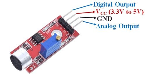
Sensor Pin Connections (VCC, GND, A0, D0)
|
Pin |
Name |
Purpose |
|
VCC |
Power |
Connect 3.3V or 5V |
|
GND |
Ground |
Connect to GND |
|
A0 |
Analog Output |
Sound level (needs ADC for Raspberry Pi) |
|
D0 |
Digital Output |
HIGH/LOW sound detection |
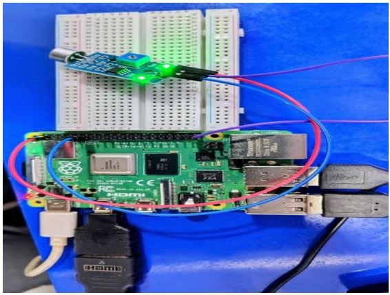
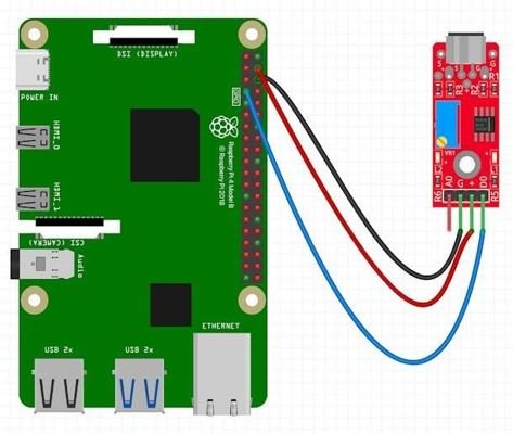
Raspberry Pi 4B with LM393 Sound Detector Sensor – Connections
|
LM393 pin |
Raspberry Pi 4B pin |
|
VCC |
3.3V (Pin 1) or 5V (Pin 2/4) |
|
GND |
GND (Pin 6) |
|
D0 |
GPIO17 (Pin 11) (any GPIO can be used) |
BOM – Bill of Materials
|
S.No. |
Component |
Quantity |
Remarks |
|
1 |
Raspberry Pi 4B |
1 |
Main controller |
|
2 |
LM393 Sound Detector Sensor |
1 |
Digital output used |
|
3 |
Jumper Wires |
6-8 |
Sensor–Pi wiring |
|
4 |
Breadboard (Optional) |
1 |
For neat connections |
|
5 |
Raspberry Pi Power Adapter |
1 |
Official 5V/3A |
|
6 |
MicroSD Card |
1 |
OS storage |
Source Code
import RPi.GPIO as GPIO
import time
SOUND_PIN = 17 # LM393 D0 connected to GPIO17
GPIO.setmode(GPIO.BCM)
GPIO.setup(SOUND_PIN, GPIO.IN)
try:
while True:
value = GPIO.input(SOUND_PIN)
if value == 1:
print(“Sound Detected”)
else:
print(“Sound Not Detected”)
time.sleep(0.2)
except KeyboardInterrupt:
GPIO.cleanup()
Test Case - 1
Test Case Name:
No Sound Detection Objective:
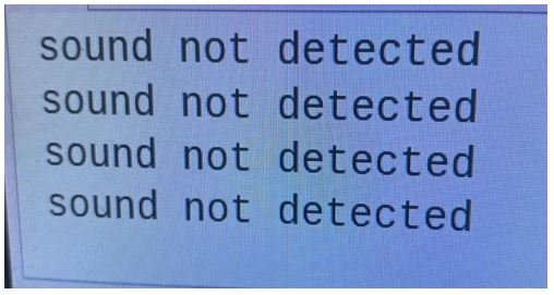
To verify that the sensor shows “Sound Not Detected” when the environment is quiet.
Test Steps:
1. Power ON Raspberry Pi 4B.
2. Run the Python program that reads D0 output.
3. Ensure the room is quiet (no clap, no loud noise).
4. Observe the terminal output.
Expected Output:
Test Case - 2
Test Case Name:
Sound Detected on Loud Noise Objective:
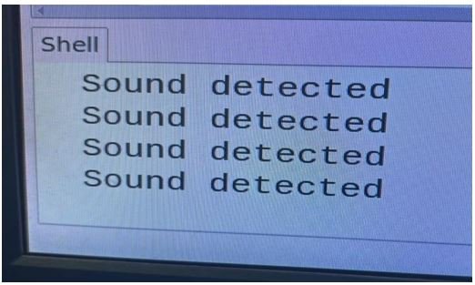
To verify that the sensor prints “Sound Detected” when a loud sound occurs.
Test Steps:
1. Keep the Python program running.
2. Clap your hands or make a loud noise near the LM393 microphone (10–20 cm).
3. Observe the terminal output.
Expected Output:
Applications of LM393 Sound Detector Sensor
1. Clap-Based Switch
Used to turn ON/OFF lights or appliances using a clap sound.
Triggers an alarm when loud noise is detected in a room or environment.
Detects unusual sounds like breaking glass, footsteps, or door knocks for security alerts.
Doorbell rings automatically when someone claps or knocks near the sensor.
Sound-based control of fans, lights, or other home devices.
6. Sound-Triggered Recording Systems
Start video/audio recording automatically when a sound is detected.
Robots can react to sound (start moving, stop, change direction).
8. Classroom or Library Noise Monitoring
Detects when sound levels exceed limits to maintain silence.
Detects abnormal machine noises in factories.