
Introduction
The purpose of this project is to measure real-time motion, tilt, rotation, and acceleration using a Raspberry Pi 4B interfaced with the MPU6050 6-axis IMU (Inertial Measurement Unit).
MPU6050 combines a 3-axis accelerometer and 3-axis gyroscope, enabling accurate detection of linear motion (X, Y, Z) and angular rotation (Roll, Pitch, Yaw).
The MPU6050 sensor has many functions over the single chip. It consists a MEMS accelerometer, a MEMS gyro, and temperature sensor. This module is very accurate while converting Analog values to digital because it has a 16bit Analog to digital converter hardware for each channel. This module is capable to capture x, y and z channel at the same time. It has an I2C interface to communicate with the host controller. This MPU6050 module is a compact chip having both accelerometer and gyro. This is a very useful device for many applications like drones, robots, motion sensors. It is also called Gyroscope or Triple axis accelerometer.
In this article, we are going to interface the MPU6050 6-Axis Gyro and Accelerometer Sensor with the Raspberry Pi 4B model and display the accelerometer and gyroscope values on the serial monitor.
Bill of Materials (BOM)
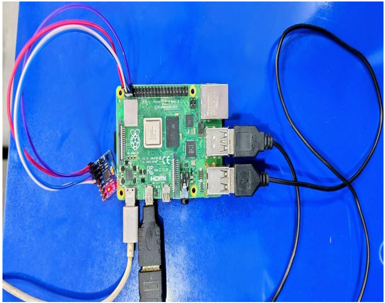
(MPU6050 Gyro Sensor Interfacing with Raspberry Pi 4B)
|
S.No |
Component Name |
Description / Specification |
Quantity |
|
1 |
Raspberry Pi 4 Model B |
4GB RAM version, Quad- core processor |
1 |
|
2 |
MPU6050 IMU Sensor Module |
3-Axis Accelerometer + 3- Axis Gyroscope |
1 |
|
3 |
Micro SD Card |
32GB |
1 |
|
4 |
Raspberry Pi Power Adapter |
5V / 3A official recommended |
1 |
|
5 |
Male-to-Female Jumper Wires |
For I2C connections (SDA, SCL, 3.3V, GND) |
4 |
|
6 |
Breadboard (Optional) |
For neat & flexible wiring |
1 |
|
7 |
HDMI Cable |
For connecting Pi to monitor |
1 |
|
8 |
Monitor / Display |
HDMI Supported |
1 |
|
9 |
USB Keyboard & Mouse |
For operating Raspberry Pi |
1 |
Pin Configuration (MPU6050 → Raspberry Pi 4B)
MPU6050 Pin Description
|
MPU6050 Pin |
Function |
Description |
|
VCC |
Power Supply |
Connects to 3.3V of Raspberry Pi (Power input) |
|
GND |
Ground |
Common ground connection |
|
SCL |
I2C Clock |
Serial Clock Line for I2C communication |
|
SDA |
I2C Data |
Serial Data Line for I2C communication |
|
INT |
Interrupt Output |
Optional interrupt pin for motion detection |
|
AD0 |
Address Select |
LOW → 0x68 (default), HIGH → 0x69 (I2C address change) |

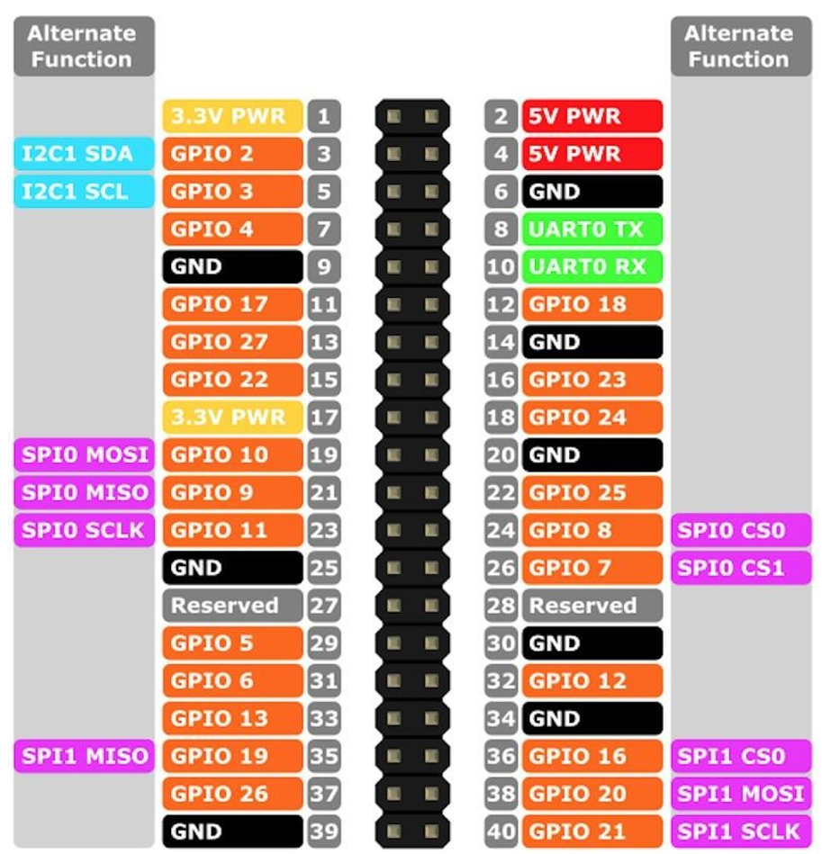
Raspberry Pi 4B GPIO Pins Used (I2C Pins)
|
Raspberry Pi Pin |
GPIO Name |
Function |
|
Pin 1 |
3.3V |
Power for sensor |
|
Pin 3 |
GPIO2 (SDA) |
I2C Data Line |
|
Pin 5 |
GPIO3 (SCL) |
I2C Clock Line |
|
Pin 6 |
GND |
Ground |
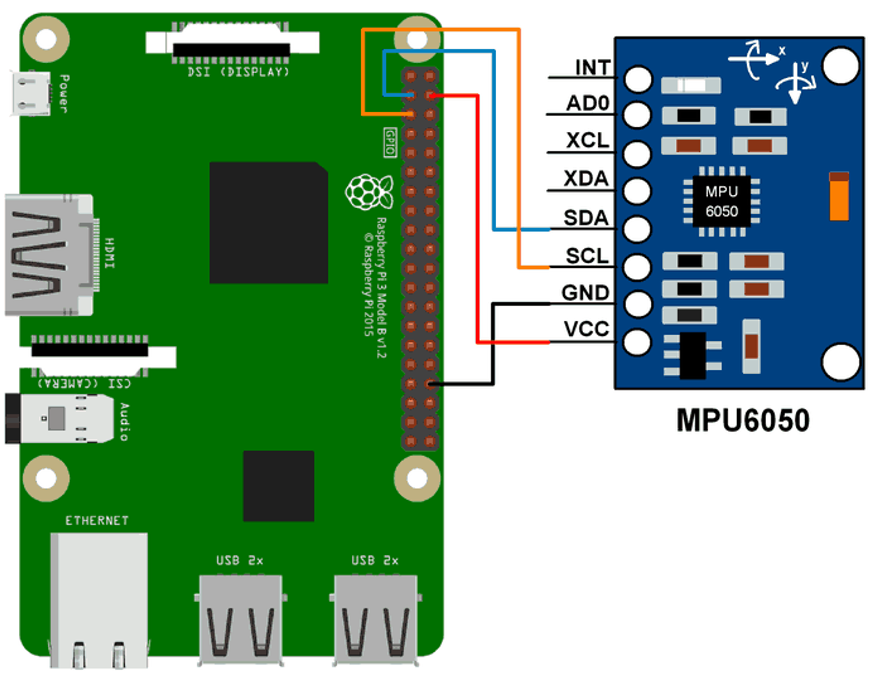
MPU6050 → Raspberry Pi 4B Pin-to-Pin Interfacing Table
| MPU6050 Pin | Raspberry Pi 4B Pin | Description |
| VCC | 3.3V (Pin 1) | MPU6050 power supply (Pi uses only 3.3V) |
| GND | GND (Pin 6) | Ground connection |
| SDA | GPIO2 – SDA1 (Pin 3) | I²C data line |
| SCL | GPIO3 – SCL1 (Pin 5) | I²C clock line |
| INT | GPIO17 (Pin 11) (Optional) | Interrupt pin (if using DMP / motion interrupt) |
| AD0 | GND (Default) | MPU6050 I²C address becomes 0x68 |
Block Diagram
Block Diagram Explanation
- Power Supply
- 5V Input → Raspberry Pi
- Raspberry Pi 3V Output → MPU6050 VCC
- Common GND
- Raspberry Pi 4B
- Controls entire system
- Runs Python code
- Reads I²C sensor values
- I²C Bus
- SDA (GPIO2 / Pin 3)
- SCL (GPIO3 / Pin 5)
- MPU6050 Sensor
- Accelerometer (X, Y, Z)
- Gyroscope (X, Y, Z)
- Temperature Sensor (Internal)
- Output / Processing
- Serial Monitor / Terminal
Description
- The Raspberry Pi 4B communicates with the MPU6050 sensor using the I²C interface, making the connection simple and reliable.
- The MPU6050 contains a 3-axis accelerometer that measures acceleration and tilt along the X, Y, and Z directions.
- It also includes a 3-axis gyroscope that detects rotation, angular movement, and orientation changes.
- The MPU6050 has an inbuilt temperature sensor, which provides the internal temperature of the sensor.
- The Raspberry Pi reads all sensor data through the SDA (GPIO2) and SCL (GPIO3) pins.
- The readings (accelerometer, gyroscope, temperature) can be displayed on the terminal, plotted as graphs, or used for motion- based applications.
- The wiring is very simple and uses only four connections: VCC, GND, SDA, and SCL.
- This setup is ideal for projects like gesture control, robot balancing, motion tracking, fall detection, and drone stabilization.
How Accelerometer and Gyroscope Values Come (with Real Values)
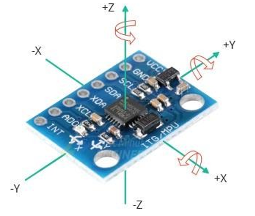
The accelerometer measures acceleration + tilt on 3 axes:
X-Axis (left–right tilt)
- Tilt right → +positive
- Tilt left → −negative
Y-Axis (forward–back tilt)
- Tilt forward → +positive
- Tilt backward → −negative
Z-Axis (up–down + gravity)
- On table: around +16384 (scaled raw), or +9.8 m/s²
- Moving up/down changes value
Real Raw Accelerometer Values – Example Readings
Case 1:
X-Axis (Left–Right Tilt)
- Tilting the sensor to the right produces a positive X
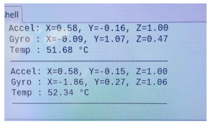
Output of the positive X (0.58) values
- Tilting the sensor to the left produces a negative X
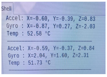
Output of the negative X (-0.60) value.
Case 2:
Y-Axis (Forward–Backward Tilt)
Tilting the sensor to the Forward produces a positive Y value
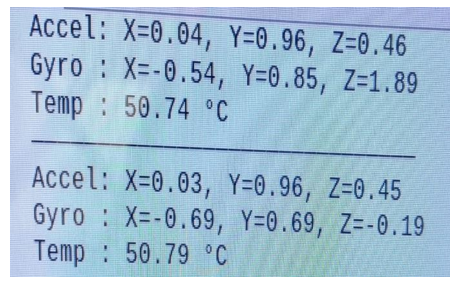
Output of the positive Y (+0.96) values
- Tilting the sensor to the Backward produces a negative
Y value.

Output of the negative Y (-0.99) values
Case 3:
Z-Axis (Up–Down Movement + Gravity)
- When the sensor is placed flat on a table, the Z-axis reads about
+16384 (raw) or +9.8 m/s², representing Earth’s gravity.
- When the sensor is moved up or down, the Z value changes depending on the acceleration.

Real Raw Gyroscope Values – Example Readings
Case 1:
Sensor Kept Still (No Rotation)
In this state, the sensor is not rotating. Small values appear due to noise.
Case 2:
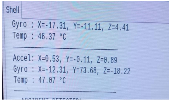
Rotating Left–Right (Y-Axis Rotation)
Rotation around the Y-axis means the MPU6050 is being moved left and right, like turning your head sideways.
Positive value (+)
- Sensor is rotating in the left direction
- output: +73.68 → strong rotation to the left
Negative value (–)
- Sensor is rotating in the right direction
- output: –38.63 → strong rotation to the right
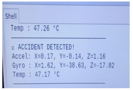
Case 3:
Fast Clockwise Rotation (Z-Axis Rotation)
Positive Value → Clockwise Rotation
If you rotate the sensor clockwise (like turning a knob to the right)
Meaning → sensor is spinning clockwise.
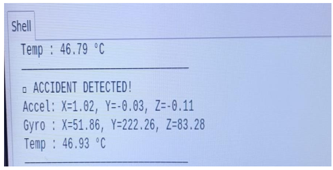
GYRO_Z = + value (output: +83.28)
Negative Value → Clockwise Rotation
If you rotate the sensor anti-clockwise (left direction): Meaning → sensor is spinning anti-clockwise.
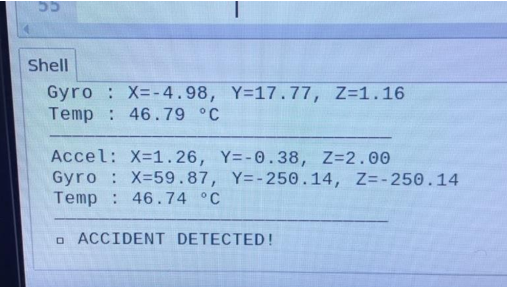
GYRO_Z = – value (output: –250.14)
Temperature value comes from inside the MPU6050 chip
- MPU6050 has an internal temperature sensor.
- It measures the temperature of the chip, not the room air
- the value will be slightly higher than room temperature.
Formula Used in Code
MPU6050 gives a raw value.
Your code converts it using this formula:
Temp C = (raw / 340.0) + 36.53

Source code
import smbus import time
PWR_M = 0x6B DIV = 0x19 CONFIG = 0x1A
GYRO_CONFIG = 0x1B INT_EN = 0x38
ACCEL_X = 0x3B ACCEL_Y = 0x3D ACCEL_Z = 0x3F TEMP = 0x41 GYRO_X = 0x43 GYRO_Y = 0x45 GYRO_Z = 0x47
Device_Address = 0x68 bus = smbus.SMBus(1)
def MPU_init():
bus.write_byte_data(Device_Address, DIV, 7)
bus.write_byte_data(Device_Address, PWR_M, 1)
bus.write_byte_data(Device_Address, CONFIG, 0)
bus.write_byte_data(Device_Address, GYRO_CONFIG, 24)
bus.write_byte_data(Device_Address, INT_EN, 1) time.sleep(0.1)
def read_word(reg):
high = bus.read_byte_data(Device_Address, reg) low = bus.read_byte_data(Device_Address, reg + 1) val = (high << 8) + low
if val > 32767: val -= 65536
return val
def read_temp():
raw = read_word(TEMP)
return (raw / 340.0) + 36.53
def read_accel():
Ax = read_word(ACCEL_X) / 16384.0 Ay = read_word(ACCEL_Y) / 16384.0 Az = read_word(ACCEL_Z) / 16384.0 return Ax, Ay, Az
def read_gyro():
Gx = read_word(GYRO_X) / 131.0 Gy = read_word(GYRO_Y) / 131.0
Gz = read_word(GYRO_Z) / 131.0 return Gx, Gy, Gz
MPU_init()
print(“MPU6050 Started…”)
while True:
temp = read_temp()
Ax, Ay, Az = read_accel() Gx, Gy, Gz = read_gyro()
print(“——————————– “)
print(“Temperature: %.2f C” % temp)
print(“Accel -> X: %.2f Y: %.2f Z: %.2f” % (Ax, Ay, Az))
print(“Gyro -> X: %.2f Y: %.2f Z: %.2f” % (Gx, Gy, Gz)) print(“—————- \n”)
time.sleep(0.5)
Applications of MPU6050
✔ Robots
It helps the robot know tilt, balance, and turn.
✔ Drones
Helps the drone stay stable and rotate smoothly.
✔ Mobile Phones
Used for screen rotation and motion games.
✔ Self-Balancing Vehicles
Helps hoverboards/Segways stay balanced.
✔ VR & Gaming
Tracks head movement and hand movement.